Data Entry
Data Entry covers how users add, convert, and manage system data in HASS Cloud using Data Input Tables, Builders, and Utilities.
Data Entry Overview
Data Entry Overview
Ways to Enter Data
There are several ways to input data into HASS Cloud.Data Input Tables
The most straightforward way is typing system data into the Data Input Tables. Using the 3 input tables gives the highest level of customization.Builders
Builders, found on the Toolbar, offer automatic system-building workflows to help users quickly build a system.Utilities
Utilities, also found on the Toolbar, offer niche calculators and legacy features for specific workflows.Data Input Tables
Data Input Tables
Workspace Behavior
The 3-table workspace is designed to offer functionality similar to common spreadsheet software. Copy/paste, delete, input, and selection behavior should feel familiar. For table-specific warning types, see Troubleshooting and Support -> Errors & Warnings.Sources Table
Use the Sources table for source-related inputs.Add a New Source
In the Sources table, click Add Source as many times as desired.Variable vs Fixed Sources
1. Select any cell in the source row you want to convert.2. Select Convert above the table and choose the target source type.
3. Or right-click the row and select Convert to Fixed Source or Convert to Variable Source. Then validate behavior with a run in Calculations.
Nodes Table
Use the Nodes table for node-based components. Nodes, sprinklers, and hose streams are entered in this table.Add a New Node
1. In the Nodes table, click Add Node to add one row.2. To add multiple rows, select the arrow next to Add Node, enter the number of rows, then select Add.
Convert to Sprinkler
1. Select any cell in the row you want to convert.2. Select Convert, then Convert to Sprinkler.
3. Or right-click the row and select Convert to Sprinkler.
Convert to Hose Stream
1. Select any cell in the row you want to convert.2. Select Convert, then Convert to Hose Stream.
3. Or right-click the row and select Convert to Hose Stream.
Convert to Node
1. Select any cell in the row you want to convert.2. Select Convert, then Convert to Node.
3. Or right-click the row and select Convert to Node. Recalculate after major conversion changes using Running a Calculation.
Pipes Table
Use the Pipes table for normal pipes, pumps, PRVs, and FPLDs. This is separate from Pipe Tables used for material and diameter standards.Add a New Pipe
1. In the Pipes table, click Add Pipe to add one row.2. To add multiple rows, select the arrow next to Add Pipe, enter the number of rows, then select Add.
Convert to Pump
1. Select any cell in the row you want to convert.2. Select Convert, then Convert to Pump.
3. Or right-click the row and select Convert to Pump.
4. To add a custom pump, input the required data under the Create New tab.
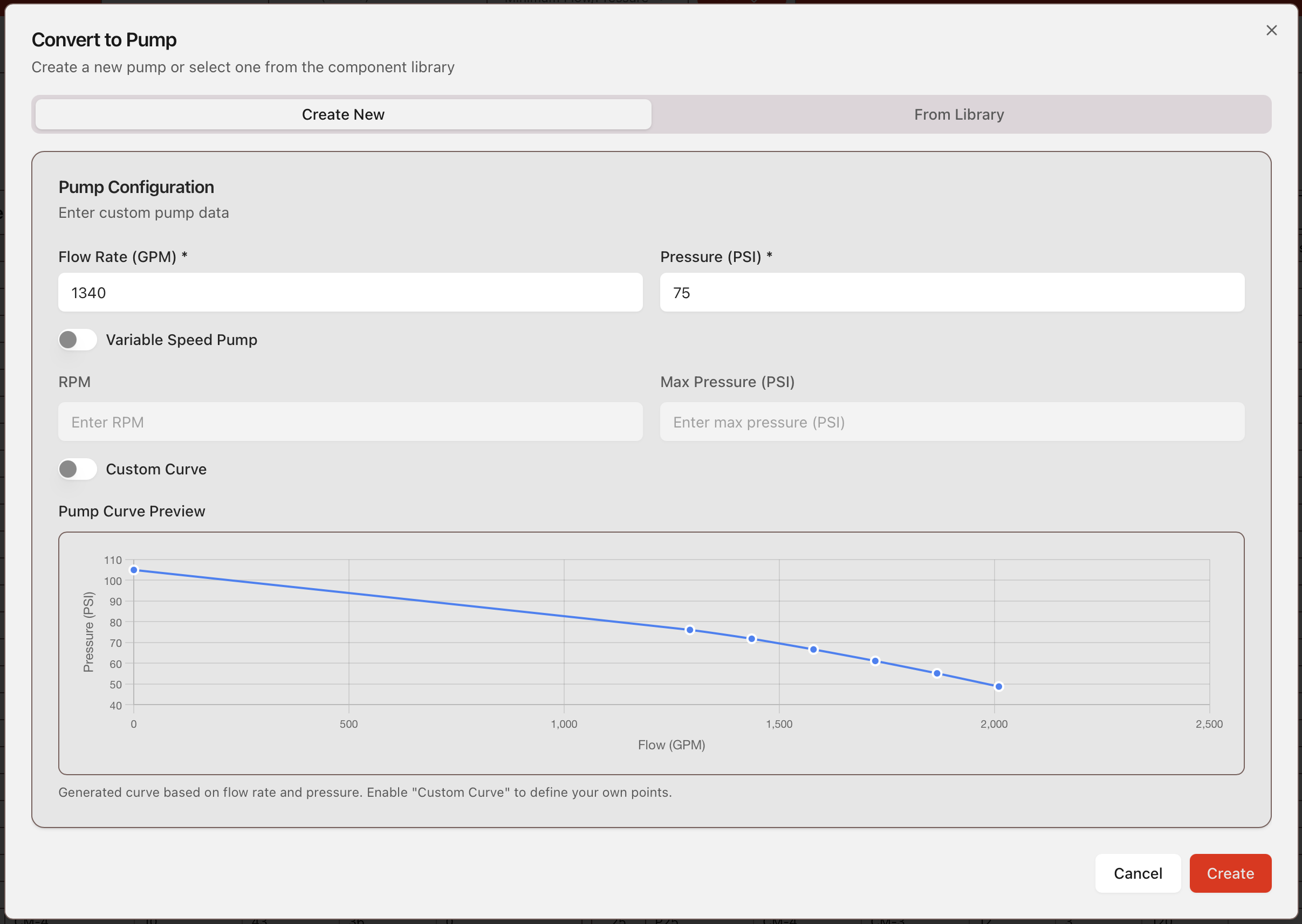
5. To add a pump from the pump library, either a default HASS pump or a previously entered custom pump, select the desired pump from the From Library tab.
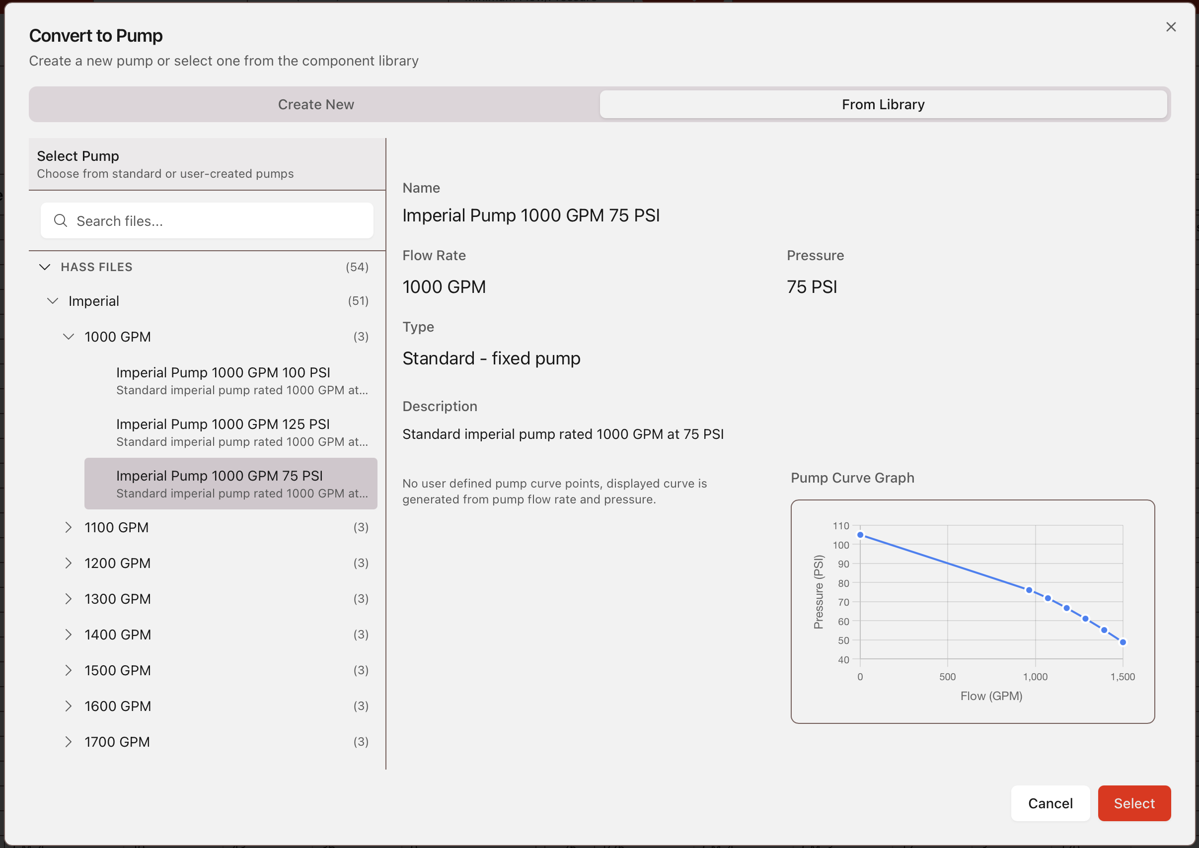
For legacy vs current default pump-curve behavior, see Calculations -> Pump Curve Model.
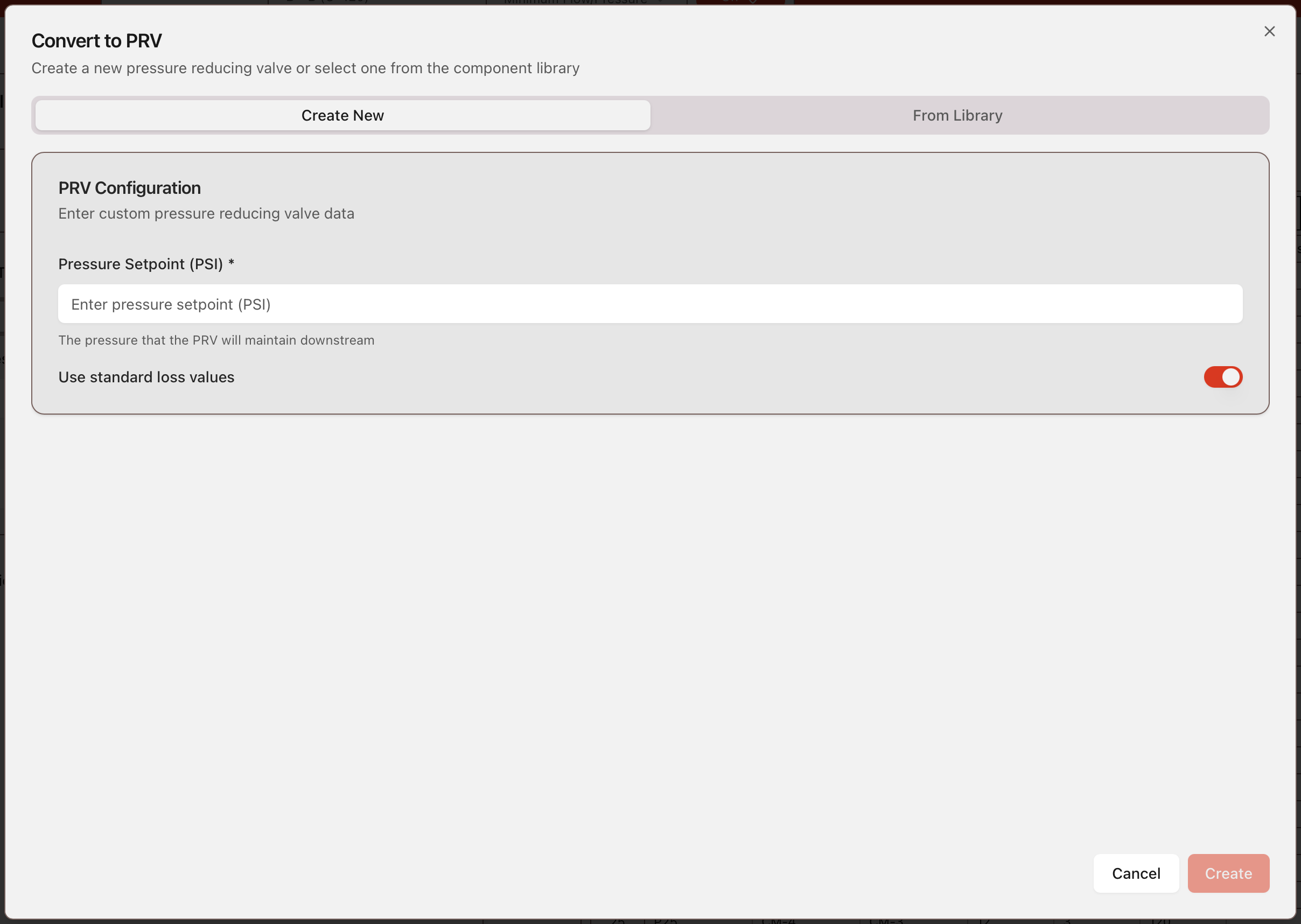
Convert to PRV
1. Select any cell in the row you want to convert.2. Select Convert, then Convert to PRV.
3. Or right-click the row and select Convert to PRV.
4. To add a custom PRV, input the required data under the Create New tab.
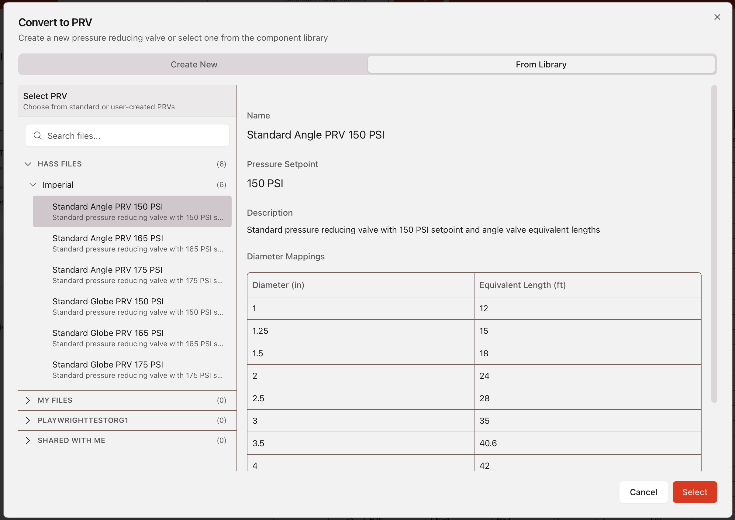
5. To add a PRV from the PRV library, either a default HASS PRV or a previously entered custom PRV, select the desired PRV from the From Library tab.
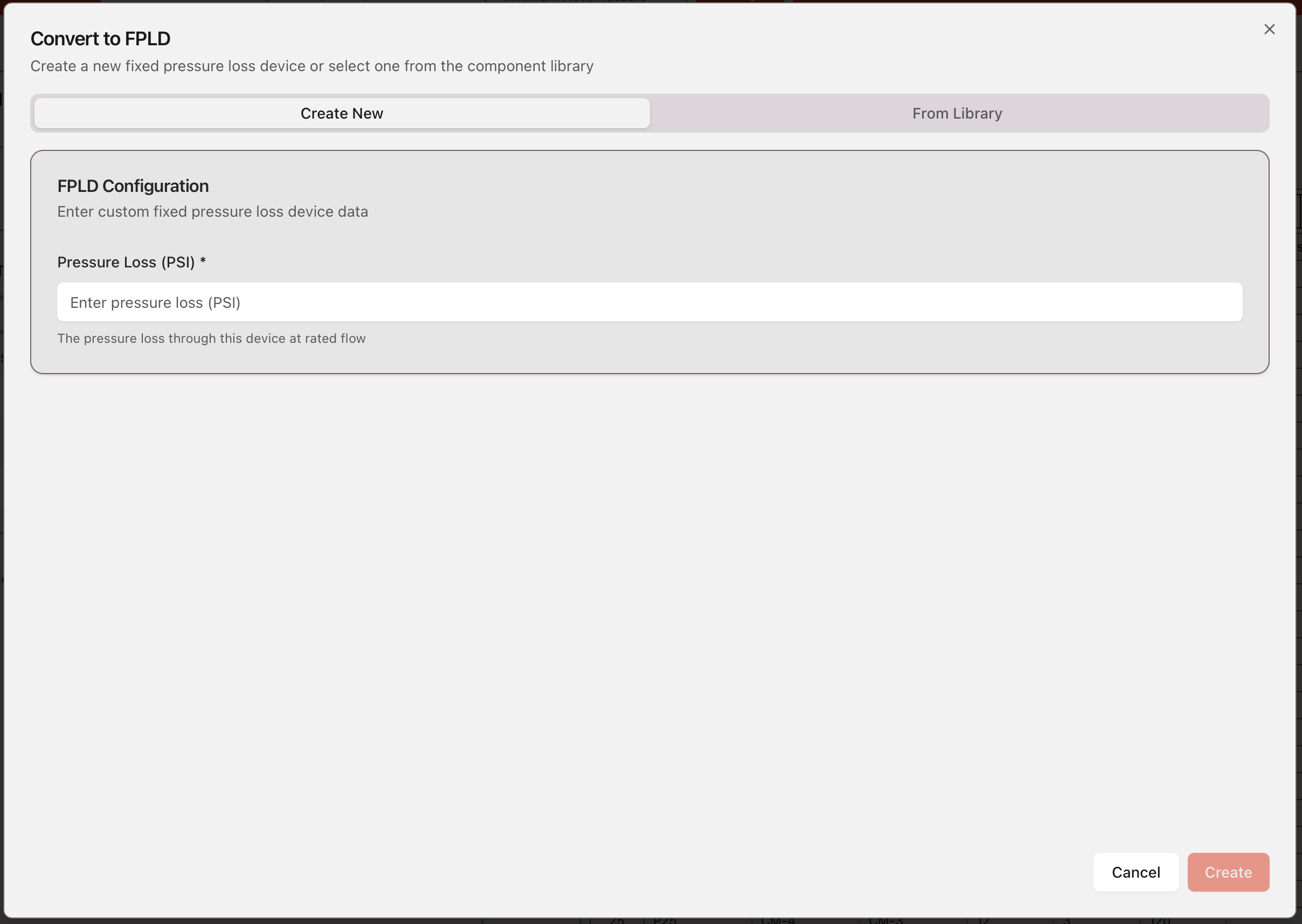
Convert to FPLD
1. Select any cell in the row you want to convert.2. Select Convert, then Convert to FPLD.
3. Or right-click the row and select Convert to FPLD.
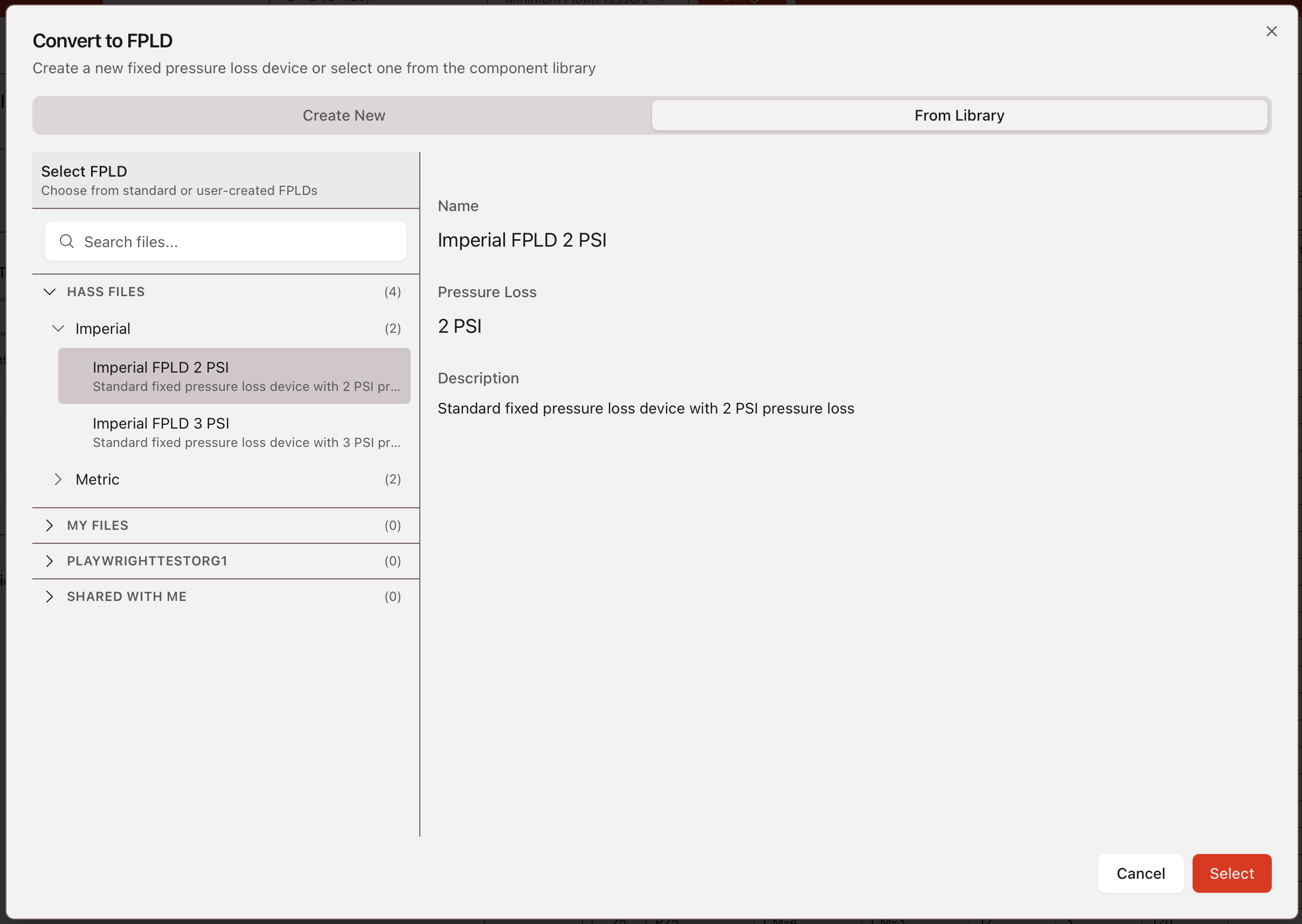
4. To add a custom FPLD, input the required data under the Create New tab.
5. To add a FPLD from the FPLD library, either a default HASS FPLD or a previously entered custom FPLD, select the desired FPLD from the From Library tab.
Convert to Normal Pipe
1. Select any cell in the row you want to convert.2. Select Convert, then Convert to Normal Pipe.
3. Or right-click the row and select Convert to Normal Pipe. If conversion errors occur, review Errors & Warnings.
Builders
Builders
All Builders open an input window from the left sidebar. Enter the required data and select Build to generate the system. Building replaces existing data in the Data Input Tables. After building, run Calculations to verify the generated system.Tree Builder
Tree Data Entry
This initial Tree Data window is the main data entry point for the Tree Builder tool. A complete pipe schedule tree-type sprinkler system can be developed using the information below.Density Requirement: The demand density required by the occupancy hazard level. Density Requirement multiplied by the sprinkler coverage gives minimum end-head flow.
Area of Demand: The operating area to be calculated. Area of Demand divided by the coverage per sprinkler gives the number of sprinklers operating. Area of Demand multiplied by density gives the minimum required sprinkler water supply. When generating a deluge tree system, input zero (0) as the Area of Demand.
Sqrt (Area) Multiplier: Multiplier used to determine the rectangular shape of the demand area with the long side parallel to branch lines. Length is determined by multiplier times the square root of the area of demand. When calculated length exceeds branch line length, all sprinklers on that branch line are opened and flowing branch lines are increased until required area of demand is reached. For deluge tree systems, input zero (0).
Total Number of Branch Lines: Total branch lines connecting to the cross main. A branch line includes all sprinklers along the same line in the same plane, without regard for cross main location. This total must include all flowing sprinklers in the area of demand.
Branch Line Spacing: Branch line spacing along the cross main. This value times spaces between branch lines gives cross main length. Generated branch lines are uniformly spaced and can be edited later in General Data Entry/Editing.
Branch Line Starter Piece Lengths: Sprinkler spacing along branch lines.
Left Starter: Length of pipe connecting cross main and first sprinkler to the left. If a sprinkler lies directly at the cross main, input a length equal to sprinkler spacing along branch lines.
Right Starter: Length of pipe connecting cross main and first sprinkler to the right. If a sprinkler lies directly at the cross main, input zero (0).
Sprinkler Spacing: Spacing along branch lines. This value times distance between lines equals coverage per sprinkler. Only sprinklers in demand area are calculated hydraulically, but inventory includes all sprinklers and fittings for the entire tree.
Number of Sprinklers: Total sprinklers per branch line and approximate cross main location relative to building center. Hydraulic analysis uses sprinklers in demand area, but inventory includes all ceiling-level sprinklers and fittings.
To Left of Cross Main: Number of sprinklers left of the cross main per branch line. If system is side-fed from left, input zero (0). If a sprinkler lies directly above cross main, it is assumed to be on the right side and should not be included in the left total.
To Right of Cross Main: Number of sprinklers right of the cross main per branch line. If system is side-fed from right, input zero (0). A sprinkler directly at cross main is assumed to be on the right and should be included in the right total.
Elevation of Sprinklers: Sprinkler discharge elevation relative to finished floor, grade, mean sea level, or another datum. All sprinklers are assumed at same elevation. For pitched branch lines, input average or worst-case and adjust later in General Data Entry/Editing.
Elevation of Branch Lines: Branch line elevation using same datum. Difference between branch line and sprinkler elevations indicates minimum drop nipple or sprig-up length. K-factor adjustments (Utility | Equivalent K factor) account for sprinkler-to-branch line connecting pipe and fittings.
Elevation of Cross Mains: Cross main elevation using same datum. Difference between cross main and branch line elevations usually equals riser nipple length.
Elevation of Source: Source node elevation. Negative elevations are permitted.
Sprinkler K-factor: Sprinkler flow coefficient. Sprinkler K-factor multiplied by square root of sprinkler pressure gives sprinkler flow.
Source: Choose whether to enter source information. Source information is not used to size pipe in Tree Builder; sizing is automatically based on Ordinary Hazard. You can toggle source entry on or off.
Custom Pipe Sizes: Input custom pipe sizes to override automatic sizing by Tree Builder. If no custom sizes are used, piping is automatically sized based on Ordinary Hazard requirements.
Grid Builder
(ESFR ONLY) BLs in Remote: Total number of branch lines in the remote area.
(ESFR ONLY) Spks per BL: Number of sprinklers on each branch line.
(ESFR ONLY) Target Pressure/Flow: Target pressure/flow for each sprinkler head. Switch between pressure and flow using the Type buttons.
Density Requirement: Demand density required by occupancy hazard level. Density requirement multiplied by sprinkler coverage gives minimum end-head flow.
Area of Demand: Operating area to be calculated. Area of Demand divided by coverage per sprinkler gives sprinklers operating, and Area of Demand multiplied by density gives minimum required sprinkler water supply.
Sqrt (Area) Multiplier: Multiplier used to determine demand area rectangle shape with long side parallel to branch lines. Length is multiplier times square root of Area of Demand. If calculated length exceeds branch line length, sprinklers on branch line are opened and flowing branch lines are increased until required area is reached.
Total Number of Branch Lines: Total branch lines connecting left and right cross mains. Generated branch lines have uniform length and diameter; adjustments can be made in General Data Entry/Editing.
Branch Line Spacing: Branch line spacing along cross mains. Distance between branch lines times spaces between branch lines gives length of each cross main and grid. Generated lines are uniformly spaced; adjustments can be made in General Data Entry/Editing.
Branch Line Len. (excl. RN): Distance between cross mains used as branch line length, excluding riser nipples joining branch line to cross mains.
Sprinkler Spacing: Distance between sprinklers along branch lines. Sprinkler spacing times line spacing equals coverage per sprinkler. Only sprinklers in demand area are calculated hydraulically, but material inventory includes all sprinklers and fittings for the full grid.
Sprinkler at C.M.?: Toggle ON to indicate sprinkler directly above cross main at top of riser nipple on a tee at branch line, and also ON if outriggers are present. Toggle OFF when sprinklers are between cross mains and fittings at riser nipple ends are a tee and elbow.
Separate Branch RN #s: Allows branch line riser nipples to be modeled as individual pipe segments rather than included in nearest branch line length. Toggle ON to allow riser nipple diameter adjustments and show riser nipple in grid diagram.
Use Bullhead Tees: Toggle ON to indicate bullhead tee usage.
Elevation of Sprinklers: Sprinkler discharge elevation relative to finished floor, grade, mean sea level, or other datum. All sprinklers are assumed at the same elevation. For pitched branch lines, enter average or worst-case, then adjust in General Data Entry/Editing as needed.
Sprinkler K-factor: Sprinkler flow coefficient. Sprinkler K-factor multiplied by square root of sprinkler pressure gives sprinkler flow.
Source on Right: Source defaults to left side of grid. Toggle ON to place source on right.
Remote Area Distance to Riser: Straight-line cross main distance from furthest flowing branch line to grid connection point. Used to locate feed main connection point on left cross main and estimate cross main friction loss. If tie-in is needed on right cross main, enter a value greater than cross main length, then connect system in General Data Entry/Editing.
Static Pressure at Source: Pressure measured at no flow during water flow test. For constant pressure source, input zero (0).
Residual Pressure at Source: Pressure measured at recorded flow during water flow test. For constant pressure source, enter desired constant pressure. This value must be greater than zero in all cases.
Flow at Source: Flow rate measured at residual pressure during water flow test. For constant pressure source, input zero (0).
Hose Allowance at Source: Manual firefighting flow reserved at source. Specify other hose streams at any node during data entry.
Custom Pipe Size: Input custom pipe sizes to override automatic sizing by Grid Builder. If no custom sizes are used, piping is automatically sized based on Ordinary Hazard requirements.
System Builder
System Builder provides an alternative data entry method that permits rapid development of data for almost any arrangement and is especially suited for complex systems.For example, System Builder can significantly reduce entry time for a three cross-main grid that would otherwise take many hours in General Data Entry/Editor.
General
Static Pressure at Source: Pressure measured at no flow during water flow test. For constant pressure source, input zero (0).
Residual Pressure at Source: Pressure measured at recorded flow during water flow test. For constant pressure source, enter desired constant pressure. This value must be greater than zero.
Flow at Source: Flow rate measured at residual pressure during water flow test. For constant pressure source, input zero (0).
Hose Allowance at Source: Manual firefighting flow reserved at source. Specify other hose streams at any node during data entry.
Elevation of Branch Lines: Branch line elevation using project datum. Difference between branch line and sprinkler elevation indicates minimum drop nipple or sprig-up length. K-factor adjustments account for sprinkler-to-branch line connecting pipe and fittings.
Elevation of Cross Mains: Cross main elevation using same datum. Difference between cross main and branch line elevation usually equals riser nipple length.
Elevation of Source: Source node elevation. Negative elevations are permitted.
Source Connection Pipe: Pipe information for connecting cross main to source.
Pipes
Pipe Code Entry
Pipe codes pair a letter shorthand with a specific pipe segment definition, so each pipe length is described only once. Fittings along a segment are entered in this window, while fittings at segment ends are defined later.BL Types
Branch Line Codes describe different branch line combinations used later. Branch line codes are made from sequences of Pipe Codes.Groups
Branch lines between cross main positions form a group, defined by branch line code and number of consecutive similar branch lines.Cross Mains
Cross main information, including diameter, riser nipple length, and fittings for each cross main to the right and left of each group, is entered in this section.Summary
Summary displays groups, branch lines, cross mains, and pipe types entered in System Builder.Utilities
Utilities
All Utilities open a calculator-style window from the left sidebar. Enter required input and select Calculate to view results in the same window. For project-level hydraulic runs, use the main Calculations workflow.System Volume Calculator
Volume Calculator Utility determines system capacity, especially for dry and antifreeze systems. It processes nominal diameters (from selected pipe table) and pipe lengths transferred from the active calculation. The utility displays a piping summary with nominal and actual diameters, pipe lengths, and calculated volume for each line in cubic inches, cubic feet, and gallons.System Split Calculator
To calculate volume for isolated sections, toggle on System Split Calculator. You can split by node or pipe to isolate and calculate only a segment rather than the entire system. After split, piping summary shows Side 1 and Side 2, where Side 1 is above selected split location and Side 2 is below it.Equivalent K-Factor
Equivalent K-Factor Calculator determines a substitute K-Factor for a sprinkler system branch line. This substitute value accounts for sprinkler K-Factor and friction loss caused by all associated pipe and fitting lengths.The utility is used for sprinklers connected to branch lines through drop nipples, riser nipples, or armovers. Because K-factors vary with operating pressure, anticipated operating pressure must be entered; default is 7 psi.
K-Factor and elevation remain independent inputs in HASS Cloud. Final calculations include elevation by using each sprinkler node's specific operating elevation.
Equivalent Branch Line
Calculates a substitute pipe to represent multiple connected pipe segments with different lengths and diameters.Branch Line K-Factor
Calculates an equivalent K-factor to represent a series of flowing nodes connected by branch line piping.Equivalent Rolled Groove H-W
Calculates a substitute Hazen-Williams coefficient to account for additional roughness introduced by rolled groove piping.Equivalent Length Conversion
Converts fitting equivalent length behavior for non-Schedule 40 pipe conditions by adjusting for diameter and Hazen-Williams differences.Water Hammer
Water Hammer Calculator
Water Hammer Calculator estimates approximate surge pressures caused by sudden water-flow deceleration, such as valve closure, pump shutdown, or control valve trip. Calculations are based on the elastic wave theories of Joukowski and Allievi, as outlined in the NFPA Fire Protection Handbook.Data Entry Modes
The calculator supports Presets and Manual modes.In Presets mode, select Hammer Pipe Table and Nominal Size. Inside Diameter, Wall Thickness, and Pipe Modulus of Elasticity are auto-filled from the table. Default values are available for ductile iron, cast iron, steel, and PVC 150. Verify auto-filled values for the actual system being analyzed.
In Manual mode, enter Inside Diameter, Wall Thickness, and Pipe Material directly. Pipe Material includes common presets (such as steel at 29,000,000 psi), and custom Modulus of Elasticity values can be entered for other materials.
Flow Properties
Enter Flow Rate (gpm) and Pipe Length (ft) for the section being evaluated.Advanced
Water Bulk Modulus defaults to 300,000 psi, which is appropriate for water at typical temperatures. Adjust this value as needed for different conditions.Calculating Results
Select Calculate to run the analysis. The pressure rise result is the surge pressure generated when flow is stopped within the critical time (the travel-and-return time of the pressure wave). Select Clear to reset fields.Rack Equivalent Pipe
Rack Sprinkler Equivalent Pipe Calculator
Provides an equivalent pipe for vertically gridded, in-rack sprinkler systems. It calculates equivalent diameter or length for a single pipe that yields the same friction loss as a gridded system with up to six vertical branch lines, including specified fittings.The calculation assumes no discharge at any node, meaning water entering at upper-left exits completely at upper-right. End nodes of each branch line are assumed to be at the same elevation.
Earthquake Bracing
Earthquake Bracing Calculator
Helps perform initial load calculations required for selecting bracing materials based on governing standards and site-specific seismic data.Entering Site Data
Enter site Latitude and Longitude (optional), then Short Period Spectral Acceleration (Ss), available from USGS Seismic Design Maps. Seismic Coefficient (Cp) is calculated automatically from Ss. Select Override to enter a custom Cp when needed.Selecting the Pipe Table
Choose Pipe Table Book and Default Pipe Table Page for the project. Selected page determines weight data used for horizontal load calculation. Override default page per pipe by adding a page prefix (for example, B4 to use page B).Adding Pipe Entries
Under Pipe Entries, add each pipe in the zone of influence with Diameter (in) and Length (ft). Use + Add for additional rows. Use Import Selected Rows to pull data from a sprinkler data file (.sdf).Example: If zone of influence includes three 1-inch branch lines at 102 ft each and cross mains of 4 x 14 ft at 2.5 inches, add one row for 1.00-inch diameter at 306 ft total length and another row for 2.50-inch diameter at 56 ft total length.